F&F automatic phase switch PF-452
- F&F automatic phase switch PF-452
Automatic phase switch PF-452 F&F
Product description
Automatic phase switch PF-452 is used to maintain continuity of power supply to a two-phase circuit in case of loss or drop of parameters of one of the supply phases.
It can serve as a controller that allows powering selected circuits when connected to one or two phases of part-phase power supply.
Operation options:
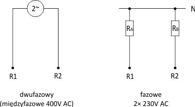
- 400 V phase-to-phase voltage output
- phase voltage output 2×230 V AC
- priority controller function - maintaining power supply to selected receivers at the correct one phase with simultaneous disconnection of power supply to secondary receivers.
Operation
Three-phase voltage (3×230 V+N) is supplied to the switch input (L1, L2, L3, N). The electronic circuit of the switch controls the voltage values of the supplied phases. Two phases with the correct parameters are directed to the outputs. The order of phase switching is not specified. After a decrease in the value of the parameters of one phase, the switch is switched to the next good phase. The switching time (appearance of voltage at the output) after the disappearance of the currently connected phase is from 0.5 to 0.8 s (during this time the consumers are powered). The Uk input is used to control the switching of contacts, protecting against the simultaneous application of two phases to one output in the case of sticking contacts of the relay.
The switch can operate in two pickup options: phase-to-phase voltage 400 V AC or phase voltages 2×230 V AC.

With one correct phase remaining, the controller operates according to the selected function:
Function A (no P-P jumper)
The correct phase is directed to both R1 and R2 output.
For the two-phase pickup option, this means no 400 V supply.
Function B (P-P jumper)
Good phase is directed only to R1 outputs.
Application: priority controller - if, due to the load, it is not possible to connect all devices to a single phase at the same time , then single-phase key receivers are connected to output R1 and will be supplied whenever at least one phase is good. Secondary receivers will be connected to output R2 and will work only when at least two phases of power supply are correct. The operation option is set by a jumper on the P-P terminals.
Technical data:
| Supply voltage | 3×(50÷450 V)+N |
| Cooperation with power generators | YES |
| Executive element | relay |
| Maximum load current | 16 A |
| Hysteresis | 5 V |
| Voltage measurement error | ±1% |
| Tripping threshold - upper adjustable | 230÷270 V |
| Tripping threshold - lower adjustable | 150÷210 V |
| Switching time | 0,5÷0,8 s |
| Operation time - adjustable | 2÷10 s |
| Output voltage - function A | 400 V AC |
| Output voltage - function B | 2×230 V+N |
| Connection | screw terminals 4.0 mm² |
| Tightening torque | 0.5 Nm |
| Power consumption | ≤ 1 W |
| Operating temperature | -25 ÷ 50 °C |
| Dimensions | 5 modules (87.5 mm) |
| Mounting | on a 35 mm rail |
| Protection degree | IP20 |


